

Introduction
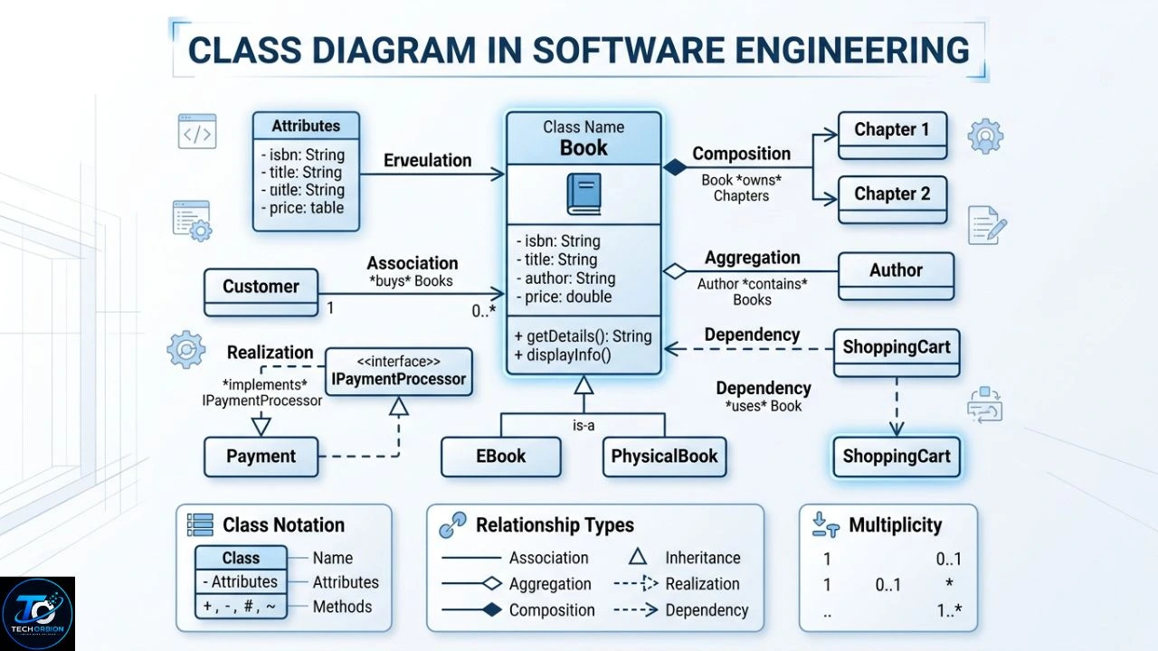
A class diagram in software engineering is a visual map that shows the structure of a software system. It helps developers understand what classes a program needs, what information those classes contain, what actions they can perform, and how they are connected.
For example, imagine you are building an online shopping website. You may have classes such as Customer, Product, Order, and Payment. A class diagram can show these classes and explain how they work together before developers start writing code.
Class diagrams are part of UML (Unified Modeling Language) and can be created using tools such as Visual Paradigm. Our guide to UML Visual Paradigm explains how these tools are used for creating and managing UML models.
Class diagrams are part of Unified Modeling Language (UML). They are commonly used during software analysis, system design, documentation, and development. A well-made diagram can make a complicated project much easier to understand because it turns technical ideas into a simple visual structure.
Table of Contents
- What Is a Class Diagram in Software Engineering?
- Main Elements of a Class Diagram
- How to Create a Class Diagram
- Benefits, Examples, and Common Mistakes
- Class Diagram vs Other UML Diagrams
- FAQs
- Conclusion

What Is a Class Diagram in Software Engineering?
A class diagram is a type of UML diagram used to describe the static structure of a software system. “Static” means it focuses on things that form the structure of the system rather than showing events happening step by step.
A class is like a blueprint for an object. For example, an application might have a Student class. That class could contain information such as the student’s name, email, and student ID. It could also define actions such as registering for a course or viewing grades.
This gives readers a direct reference to the official UML specification instead of relying on a third-party explanation.
A class diagram puts these ideas into a visual format. Developers can see the important classes, their properties, their operations, and the relationships between them.
Why Are Class Diagrams Important?
Software projects can become difficult to understand when they contain many classes and relationships. A class diagram provides a high-level view of the system.
Developers can use it to:
- Plan a software system before coding
- Understand relationships between classes
- Discuss system architecture with team members
- Find design problems early
- Document an existing application
- Explain software structure to students or clients
- Make future maintenance easier
A class diagram does not replace source code. Instead, it acts as a design and communication tool that helps developers think about the structure before or during implementation.
Main Elements of a Class Diagram
Understanding the basic elements is the most important step for beginners. A class diagram may look complicated at first, but most diagrams are built from a few common parts.
Classes
A class represents a group of objects that share similar data and behavior.
For example, an online bookstore could have:
- Customer
- Book
- Order
- Payment
- ShoppingCart
A class is usually shown as a rectangle divided into sections.
A simple Customer class could look like this:
+----------------------+
|       Customer       |
+----------------------+
| - name               |
| - email              |
| - customerID         |
+----------------------+
| + login()            |
| + updateProfile()    |
+----------------------+
The first section contains the class name. The second contains attributes, and the third contains operations or methods.
Attributes
Attributes describe the data stored by a class.
For a Customer class, attributes might include:
- Name
- Phone number
- Customer ID
For a Product class, attributes could include:
- Product name
- Price
- Product ID
- Stock quantity
Attributes describe what an object knows.
Methods or Operations
Methods describe what a class can do.
For example, a Customer class might have:
login()logout()updateProfile()
A ShoppingCart class might have:
addItem()removeItem()calculateTotal()
In software development, these operations are eventually implemented as functions or methods in a programming language.
Visibility
Class diagrams can also show who can access an attribute or operation.
Common UML visibility symbols include:
| Symbol | Meaning |
|---|---|
+ | Public |
- | Private |
# | Protected |
~ | Package |
For example:
+ login()
- password
# accountID
This tells developers something about the access level of each member.
Relationships Between Classes
Relationships are one of the most important parts of a class diagram. They explain how different classes are connected.
Common relationships include:
- Association
- Aggregation
- Composition
- Inheritance
- Dependency
Choosing the correct relationship helps the diagram represent the actual software design.
Association
An association shows that two classes are connected in some way.
For example:
Customer -------- OrderThis can mean that a customer places or owns orders.
Associations can also show multiplicity. For example, one customer may have many orders.
Customer 1 -------- 0..* OrderHere, 1 means one customer, while 0..* means zero or more orders.
Inheritance
Inheritance represents an “is-a” relationship.
For example:
             Vehicle
                |
        ----------------
        |              |
       Car          Motorcycle
A Car is a type of Vehicle, and a Motorcycle is also a type of Vehicle.
The child classes can inherit common properties or behaviors from the parent class.
Aggregation
Aggregation represents a whole-part relationship where the parts can exist separately.
For example, a Team may contain Player objects. A player could still exist even if the team is removed.
Composition
Composition is a stronger whole-part relationship.
For example, an Order may contain OrderItem objects. If the order is permanently removed from the system, its order items may also be removed.
The difference between aggregation and composition is important because it communicates different ownership and lifetime relationships.
How to Create a Class Diagram
Creating a useful diagram starts with understanding the system. Do not begin by adding random classes. First decide what the software needs to do.

Step 1: Identify the Main Objects
Read the requirements and look for important nouns.
For an online food delivery system, you might identify:
- Customer
- Restaurant
- FoodItem
- Order
- DeliveryDriver
- Payment
These can become potential classes.
Not every noun needs to become a class. Use your understanding of the system to decide which concepts need their own data and behavior.
You can use a dedicated Visual Paradigm UML tool to create classes, attributes, methods, and relationships visually.
Step 2: Add Attributes
Next, think about what information each class needs.
For example:
Customer
- customerID
- name
- phone
Restaurant
- restaurantID
- name
- address
- rating
Order
- orderID
- orderDate
- totalAmount
- status
Keep the first version simple. You can add details later.
Step 3: Add Methods
Now identify important actions.
For example:
Customer
- login()
- placeOrder()
Order
- calculateTotal()
- updateStatus()
Payment
- processPayment()
- refund()
Methods should represent meaningful behavior rather than every tiny operation in the application.
Step 4: Connect the Classes
Think about how the classes interact.
For example:
Customer -------- Order
Order -------- Payment
Restaurant -------- FoodItem
Order -------- FoodItem
Then decide what relationship type and multiplicity make sense.
Step 5: Review the Diagram
Finally, check whether the diagram matches the requirements.
Ask yourself:
- Are all important classes included?
- Are any classes unnecessary?
- Are attributes placed in the correct classes?
- Are methods meaningful?
- Are relationships accurate?
- Is the diagram easy to read?
A good class diagram should help another developer understand the system without needing a long explanation.
Benefits, Examples, and Common Mistakes
Class diagrams can be useful throughout the software development process. They are especially valuable when a project has many objects, relationships, or developers.
Benefits of Class Diagrams
Better planning: Developers can think about the structure before writing large amounts of code.
Clear communication: Team members can discuss system components using a shared visual model.
Easier documentation: A class diagram can provide a quick overview of an application’s architecture.
Early problem detection: Modeling may reveal missing classes, unnecessary dependencies, or poorly designed relationships.
Helpful for maintenance: New developers can use diagrams to understand an existing system more quickly.
Real-Life Example: Library Management System
Consider a library application.
The system may contain these classes:
| Class | Important Attributes | Example Methods |
|---|---|---|
| Member | memberID, name, email | borrowBook() |
| Book | ISBN, title, author | checkAvailability() |
| Librarian | employeeID, name | addBook() |
| Loan | loanID, issueDate, dueDate | calculateFine() |
A member can borrow books. A book can be involved in multiple loans over time. A librarian can manage books and members.
The diagram gives developers a simple structure to work from before implementation.
Common Mistakes
One common mistake is adding too many classes. A diagram with hundreds of elements can be difficult to understand. Break large systems into smaller diagrams when necessary.
Another mistake is confusing attributes with methods. An email address is data, so it belongs as an attribute. sendEmail() is an action, so it belongs as an operation.
A third mistake is using inheritance when it is not necessary. Just because two classes have similar properties does not always mean one should inherit from the other.
Another problem is forgetting multiplicity. Saying that a Customer is related to an Order is less useful than explaining whether one customer can have one order or many orders.
Expert Tips
Start with the most important classes and relationships. Do not try to model every implementation detail.
Use meaningful names. Customer is much clearer than C1.
Keep responsibilities logical. A class should not be responsible for unrelated tasks.
Update diagrams when major design changes occur. An outdated diagram can be worse than having no diagram because it may give developers incorrect information.
For large projects, consider creating multiple focused diagrams instead of one huge diagram.
Class Diagram vs Other UML Diagrams
A class diagram is only one type of UML diagram. Other diagrams focus on different aspects of a software system.
| UML Diagram | Main Purpose | Example Question |
|---|---|---|
| Class Diagram | System structure | What classes exist? |
| Use Case Diagram | User requirements | What can users do? |
| Sequence Diagram | Object interaction | How do objects communicate? |
| Activity Diagram | Workflow | What steps happen in a process? |
| State Machine Diagram | Object states | How does an object change state? |
| Component Diagram | Software components | What major components exist? |
| Deployment Diagram | Physical deployment | Where does the software run? |
A class diagram focuses mainly on structure. A sequence diagram, in contrast, focuses on interaction over time.
For example, a class diagram might show that Customer and Order are related. A sequence diagram could show the actual messages exchanged when the customer places an order.
Using multiple UML diagrams can provide a more complete picture of a complex application.
When Should You Use a Class Diagram?

Class diagrams are particularly useful when:
- Designing object-oriented software
- Planning database-related application structures
- Explaining relationships between system objects
- Documenting an existing application
- Teaching object-oriented programming
- Discussing architecture with developers
For a tiny script, creating a detailed class diagram may not be worth the time. The value increases as the software becomes larger or more complex.
FAQs
1. What is a class diagram in software engineering?
A class diagram is a UML model that visually represents the static structure of a software system. It can show classes, attributes, methods, and relationships between classes.
2. What are the main parts of a class diagram?
The main parts include classes, attributes, operations, relationships, and visibility information. Relationships can include association, inheritance, aggregation, composition, and dependency.
3. Why are class diagrams important?
They help developers plan software, understand system structure, communicate design ideas, document applications, and identify design problems before or during development.
4. Is a class diagram the same as a flowchart?
No. A class diagram describes the structure of a system, while a flowchart generally shows the steps in a process or algorithm. UML activity diagrams are more closely related to workflow modeling.
5. Can beginners create class diagrams?
Yes. Beginners can start with simple classes containing names, a few attributes, and basic relationships. Learning the basic UML symbols and practicing with small real-world examples makes the process easier.
Conclusion
A class diagram in software engineering provides a clear visual picture of how a software system is organized. It shows important classes, their data, their behavior, and the relationships connecting them.
The best diagrams are not necessarily the most detailed ones. They are the ones that clearly communicate the design. Start with the main classes, add meaningful attributes and methods, choose relationships carefully, and keep the model easy to read.
Whether you are designing an online store, library system, banking application, or school management platform, class diagrams can help turn a complicated software idea into a structure that developers can understand and build.
