

Introduction
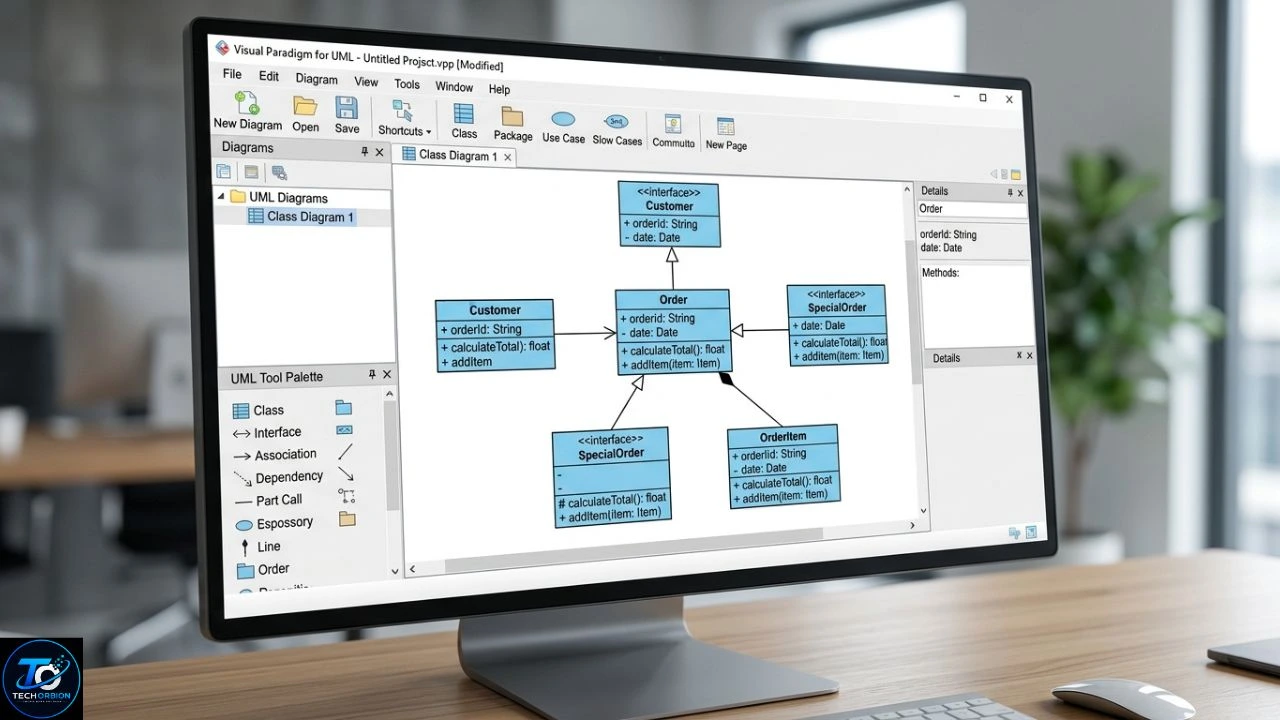
Visual Paradigm UML is a practical way to create, organize, and understand UML diagrams for software and system design. UML stands for Unified Modeling Language, a standard visual language used to describe software structure, behavior, and relationships. The Object Management Group (OMG) maintains the UML specification and provides official UML resources.
Visual Paradigm is a practical tool for creating, organizing, and understanding UML diagrams for software and system design.
Visual Paradigm makes UML modeling easier by providing tools for creating diagrams such as class, use case, sequence, activity, state machine, component, deployment, and package diagrams.
Whether you are a student learning software engineering or a developer planning a real application, UML can help you turn complicated ideas into simple visual models. This guide explains what Visual Paradigm UML is, which diagrams you can create, how to use them, their benefits and limitations, and practical tips for making better UML models.
Table of Contents
- What Is Visual Paradigm UML?
- Main UML Diagrams in Visual Paradigm
- How to Create UML Diagrams in Visual Paradigm
- Benefits, Drawbacks, and Common Mistakes
- Visual Paradigm UML vs Other Modeling Methods
- FAQs
- Conclusion
What Is Visual Paradigm UML?

Visual Paradigm UML combines the UML modeling language with software designed to help users create and manage visual models. Instead of drawing UML shapes manually, you can use a dedicated modeling environment to place elements, connect relationships, and organize different parts of a system.
UML itself is not a programming language. It is a visual modeling language. It helps developers and other team members understand what a system should do and how its different parts fit together. OMG describes UML as a standard for visualizing, specifying, and documenting software and systems.
If you are new to the topic, our guide to UML Visual Paradigm explains the basics of UML modeling and how Visual Paradigm can be used to create different diagrams.
Visual Paradigm’s UML tool supports a wide range of diagram types. Its current toolset includes use case, class, sequence, communication, activity, state machine, component, deployment, package, object, composite structure, timing, interaction overview, and profile diagrams.
Why Is UML Important?
Imagine that you want to build an online shopping website. There may be customers, products, orders, payments, delivery services, and administrators.
Explaining all these parts in normal sentences could become difficult. A UML diagram can show them visually.
For example, a class diagram can show the relationship between Customer, Order, and Product. A use case diagram can show what a customer can do. A sequence diagram can show what happens when the customer places an order.
This makes UML useful for:
- Planning software before coding
- Understanding project requirements
- Explaining ideas to a development team
- Documenting an existing system
- Finding design problems early
- Showing relationships between system components
- Teaching software engineering concepts
Main UML Diagrams in Visual Paradigm
One of the biggest advantages of using Visual Paradigm is that you can create many UML diagram types in one modeling environment. However, beginners do not need to learn every diagram at once.
Start with the diagrams that answer the most important questions about your project. Visual Paradigm’s official UML tool specifically supports common diagrams such as use case, class, sequence, activity, component, deployment, and state machine diagrams.
Use Case Diagram
A use case diagram explains what users or other external systems can do with an application.
For example, consider a school management system. You might have three actors:
- Student
- Teacher
- Administrator
A student may be able to view grades and attendance. A teacher may enter grades and attendance. An administrator may manage users and courses.
The diagram gives you a quick picture of the system from the user’s point of view. Visual Paradigm describes use cases as ways to capture functional requirements and shows actors connected with the functions they interact with.
Class Diagram
A class diagram shows the structure of a software system. It can display classes, attributes, operations, and relationships.
For an online store, a simple model might contain:
| Class | Example Attributes | Example Operations |
|---|---|---|
| Customer | Name, Email | Login(), UpdateProfile() |
| Product | Name, Price | UpdatePrice() |
| Order | Order ID, Date | CreateOrder() |
| Payment | Amount, Status | ProcessPayment() |
A class diagram works like a blueprint for the structure of an application. Visual Paradigm explains that its class diagram tool can model classes, attributes, and operations that may be required to build a software system.
Sequence Diagram
A sequence diagram shows how users, objects, or systems communicate over time.
Suppose a customer logs into an online store. The interaction might happen like this:
- The customer enters an email and password.
- The website sends the information to an authentication service.
- The authentication service checks the database.
- The database returns the account information.
- The authentication service sends a result to the website.
- The website displays the customer’s account.
A sequence diagram makes this order easy to see. Visual Paradigm describes sequence diagrams as a way to visualize interactions between users, systems, and subsystems through messages passed between objects or roles.
Activity Diagram
An activity diagram is useful for showing a process or workflow.
For example, an online shopping process could be:
Select Product → Add to Cart → Checkout → Payment → Order Confirmation
Activity diagrams become especially helpful when a process has decisions.
For example:
Payment Successful?
- Yes → Confirm Order
- No → Show Payment Error
Visual Paradigm describes its activity diagram as a flowchart-based way to model the flow of control.
Other Useful UML Diagrams
Large projects may require additional diagrams. For example, component diagrams can show the structure of software components, while deployment diagrams can show how software is deployed on hardware or server nodes. Package diagrams can help organize models and show dependencies between subsystems.
State machine diagrams are useful when an object changes between different states based on events. Timing diagrams can help describe how objects behave over a period of time, particularly in real-time systems.
You should not create every possible diagram simply because the software allows it. Each diagram should have a clear purpose.
How to Create UML Diagrams in Visual Paradigm
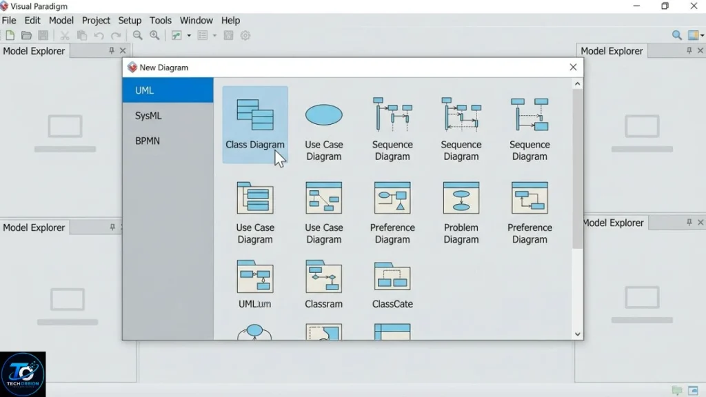
Creating your first diagram is easier when you follow a simple process. The biggest mistake beginners make is opening a blank canvas and immediately adding random shapes.
Instead, understand the system first.
Step 1: Understand the Requirements
Before creating a diagram, write down what the system needs to do.
For a food delivery app, you might identify:
- Customers
- Restaurants
- Delivery drivers
- Orders
- Payments
- Order tracking
Then think about how these parts interact.
Step 2: Select the Right Diagram
Choose a diagram based on the question you want to answer.
| Question | Recommended UML Diagram |
|---|---|
| What can users do? | Use Case |
| What classes exist? | Class |
| How do objects communicate? | Sequence |
| How does a process work? | Activity |
| How does an object change state? | State Machine |
| What software components exist? | Component |
| Where is software deployed? | Deployment |
| How are models organized? | Package |
This simple approach prevents you from using the wrong diagram.
Step 3: Add the Main Elements
Start with the most important parts.
For a class diagram, you might begin with Customer, Order, and Product. Do not add dozens of classes immediately.
Once the basic structure is correct, add more details.
Step 4: Add Relationships
Relationships explain how elements connect.
For example, a customer can place orders, and an order can contain products.
Make sure the relationship actually represents the system. Do not add lines just to make the diagram look complete.
Step 5: Review the Model
After creating the diagram, read it as if you were someone who had never seen the project.
Ask yourself:
- Are the names easy to understand?
- Is anything unnecessary?
- Are relationships correct?
- Does the diagram match the requirements?
- Can another person understand it quickly?
If the answer is no, simplify it.
Visual Paradigm Online
Visual Paradigm also provides an online UML diagram tool. Its online environment supports diagrams such as class, use case, sequence, activity, deployment, component, state machine, and package diagrams. It also provides features such as inline editing and quick shape creation.
This can be useful when you want to create UML diagrams through a web-based environment rather than relying only on a desktop modeling workflow.
Benefits, Drawbacks, and Common Mistakes
Visual Paradigm UML can make system design much easier, but a modeling tool does not automatically create good software architecture. You still need to understand your requirements and make sensible design decisions.
Benefits of Visual Paradigm UML
1. Easier visual planning
Diagrams can make complicated systems easier to understand before development begins.
2. Many diagram types
The tool supports a broad collection of UML diagrams, allowing you to choose a model that fits your specific problem.
3. Better communication
A diagram can help developers, students, clients, and other team members discuss the same system using a shared visual representation.
4. Useful documentation
UML models can become part of a project’s technical documentation.
5. Helpful for students
Students can use UML diagrams to practice software engineering concepts and understand how requirements connect to system design.
Drawbacks
UML also has limitations.
Large diagrams can become difficult to read. A diagram containing too many classes, relationships, and labels may be technically detailed but practically confusing.
Another problem is outdated documentation. If a development team changes the software but does not update important models, the diagrams may no longer represent the real system.
There is also a learning curve. Beginners need time to understand UML symbols, relationships, and diagram rules.
Finally, not every project needs extensive UML documentation. A small application may only need a few simple models.
Common Mistakes to Avoid
Trying to show everything in one diagram: Create separate diagrams when the system becomes too large.
Using the wrong diagram: Decide what you want to explain before choosing a UML diagram.
Adding unnecessary details: Keep the model focused on its purpose.
Ignoring relationships: A collection of boxes is not enough. Relationships often carry important meaning.
Failing to update diagrams: Important models should stay consistent with major changes in the software.
Treating UML as code: UML helps you plan and explain software, but it does not replace programming, testing, or requirements analysis.
Practical Tips for Better UML Models
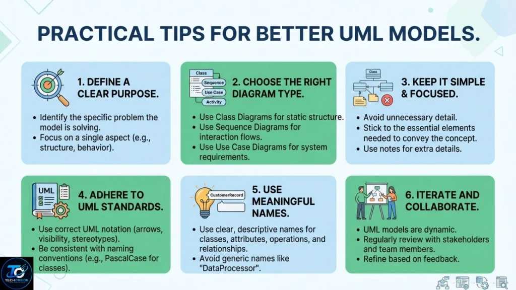
Keep names simple and meaningful. Customer, Order, and Payment are easier to understand than unclear abbreviations.
Use one diagram to answer one main question. If readers need several minutes just to understand what a diagram is showing, it probably needs simplification.
Also, start small. Build a basic model first and add details as your understanding of the project improves.
For students, it is better to understand why a relationship exists than to memorize every UML symbol. For developers, the model should support real development rather than become paperwork that nobody uses.
Visual Paradigm UML vs Other Modeling Methods
Visual Paradigm is a dedicated modeling solution, but it is not the only way to create diagrams. You can also use general-purpose diagramming applications or draw simple models manually.
The right option depends on the size and needs of your project.
| Feature | Visual Paradigm UML | General Diagram Tool | Manual Drawing |
|---|---|---|---|
| UML-specific support | Yes | Varies | No |
| UML symbols | Built in | May be available | Manual |
| Multiple diagram types | Strong | Depends on tool | Time-consuming |
| Large projects | More suitable | Can become difficult | Difficult |
| Relationship modeling | Dedicated features | Often basic | Manual |
| Learning UML | Good | Depends on tool | Basic |
| Documentation | Useful | Depends on tool | Limited |
For a simple classroom exercise, almost any diagramming method may work. For a larger software project, dedicated UML modeling features can save time and make models easier to maintain.
Visual Paradigm makes UML modeling easier through its dedicated Visual Paradigm UML tool, which supports many different types of diagrams.
Visual Paradigm also provides model-element referencing, allowing diagrams and model elements to be connected through internal references. Its official documentation describes these references as useful for connecting different project artifacts and related documentation.
UML Standard and Visual Paradigm
It is important to understand the difference between UML and Visual Paradigm.
UML is the modeling language. Visual Paradigm is the software used to create models.
The UML specification is maintained by the Object Management Group. OMG’s specifications catalog currently lists UML 2.5.1 as the formal UML specification, adopted in December 2017.
This distinction matters because learning UML concepts gives you knowledge that can be applied beyond one particular software tool.
FAQs
1. What is Visual Paradigm UML?
Visual Paradigm UML refers to using Visual Paradigm’s modeling tools to create UML diagrams and models for software and system design. It supports many common UML diagram types.
2. What is UML used for?
UML is used to visually describe, specify, and document software and systems. It can represent system structure, behavior, requirements, interactions, and relationships.
3. Which UML diagram should beginners learn first?
A use case diagram is a good starting point because it helps you understand what users can do in a system. After that, class, sequence, and activity diagrams are useful for learning structure, communication, and workflows.
4. Can Visual Paradigm create class and sequence diagrams?
Yes. Visual Paradigm’s UML tools support both class diagrams and sequence diagrams, along with many other UML diagram types.
5. Is Visual Paradigm the same thing as UML?
No. UML is a standard modeling language, while Visual Paradigm is software that provides tools for creating UML models. UML is maintained through the Object Management Group’s specification process.
Conclusion
Visual Paradigm UML provides a practical way to turn software ideas into clear visual models. From use case and class diagrams to sequence, activity, component, and deployment diagrams, different UML models can explain different parts of a system. Visual Paradigm supports a broad range of these diagrams and provides dedicated features for creating and organizing them.
The key is not to create as many diagrams as possible. Instead, choose the model that answers the question you are trying to solve. Keep diagrams simple, use meaningful names, check relationships carefully, and update important models when the software changes.
If you are a beginner, start with use case, class, sequence, and activity diagrams. Once these become comfortable, you can explore more advanced UML models. Used thoughtfully, Visual Paradigm can make software planning, communication, and documentation much easier.
